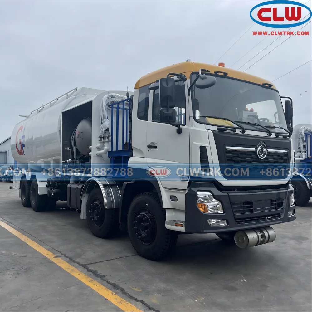
Aircraft Refueler 6×4 15000-20000L Aviation Fuel Jet A-1
The 6×4 aircraft refueler truck is a professional aviation fuel service vehicle designed for aircraft refueling, Jet A-1 fuel delivery, airport ground support and aviation fuel distribution operations.
•With a tank capacity of 15,000 to 20,000 liters, the 6×4 configuration provides a practical balance between fuel capacity, maneuverability, equipment layout and operating cost.
•This aircraft refueling truck can be equipped with aviation fuel pump, filter separator, flow meter, hose reel, underwing coupler, overwing nozzle, static bonding and grounding system, emergency shut-off device, deadman control, anti-overflow protection, additive injection system, bottom loading system and optional lifting platform.
•The vehicle is suitable for airports, airfields, helicopter bases, aviation fuel service companies and ground support operations requiring a compact but professional refueling solution.
aircraft refueler truck Overview
A 6×4 aircraft refueler truck is not a standard fuel tanker. It is a complete aviation fuel handling system mounted on a truck chassis. The vehicle is designed to store, transfer, filter, measure and dispense aviation fuel safely during aircraft ground refueling operations.
The refueling system can be configured according to fuel type, required flow rate, operating temperature, refueling method, chassis payload and airport operation procedure. For Jet A-1 and aviation kerosene service, key design points include fuel cleanliness, static electricity control, emergency shutdown, metering accuracy, safe hose handling and tank manufacturing quality.
Compared with larger 8×4 aircraft refuelers, the 6×4 model offers a more compact structure and better maneuverability in limited airport service areas, while still allowing professional refueling equipment and safety systems to be installed.
Main Specifications of 6x4 Aircraft Refueler Truck
| Item | Specification |
|---|---|
| Product Name | 6×4 Aircraft Refueler Truck |
| Drive Type | 6×4 |
| Tank Volume | 15-20 CBM |
| Fuel Type | Jet A-1, aviation kerosene, diesel or other fuel |
| Tank Material | Carbon steel, stainless steel or aluminum alloy |
| Tank Structure | Single compartment or multiple compartments |
| Tank Shape | Elliptical or round tank body |
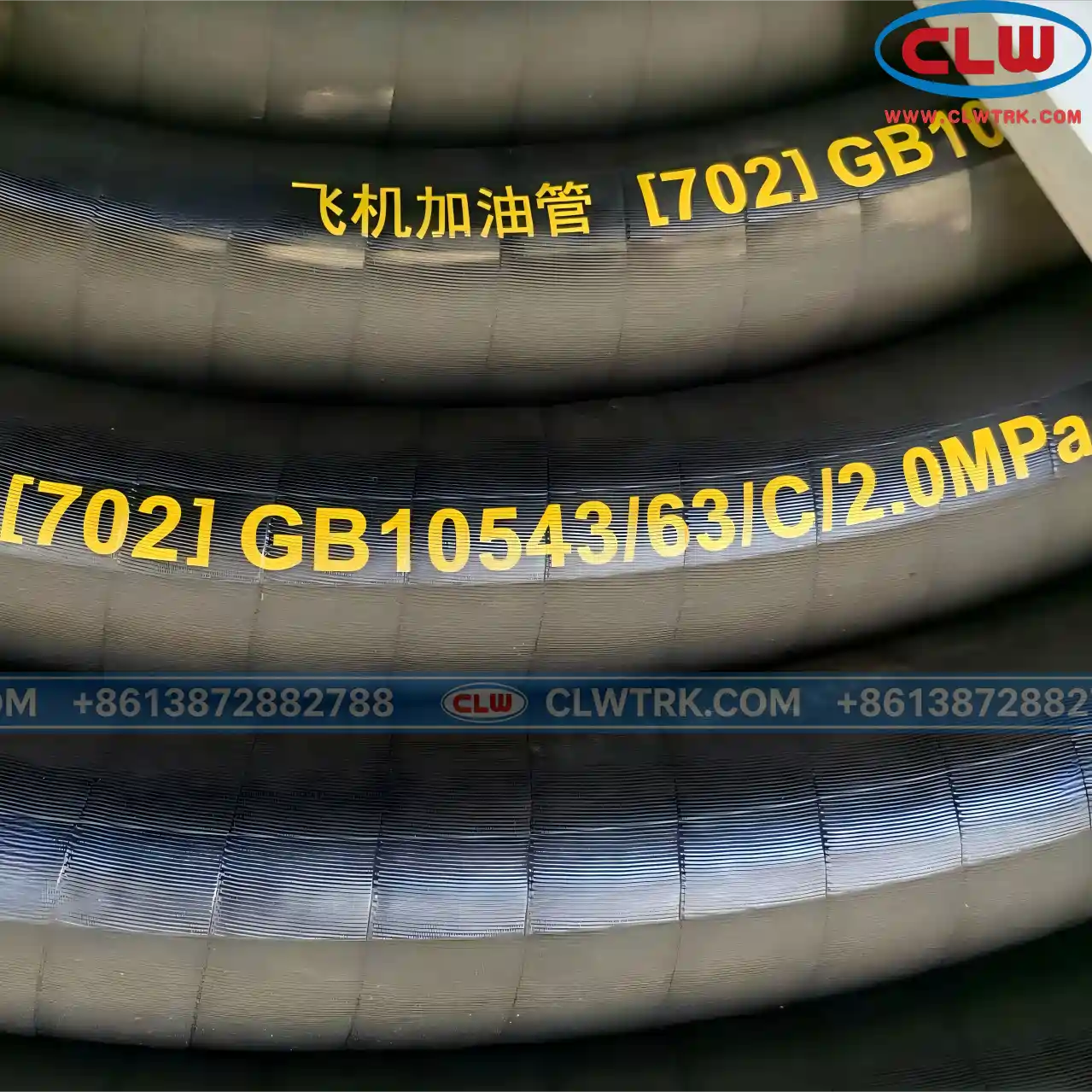
| Refueling Method | Underwing refueling and/or overwing refueling |
| Fuel Pump | PTO-driven, hydraulic or independent power pump system |
| Filtration System | Filter separator for water and particle removal |
| Flow Meter | Mechanical or digital flow meter |
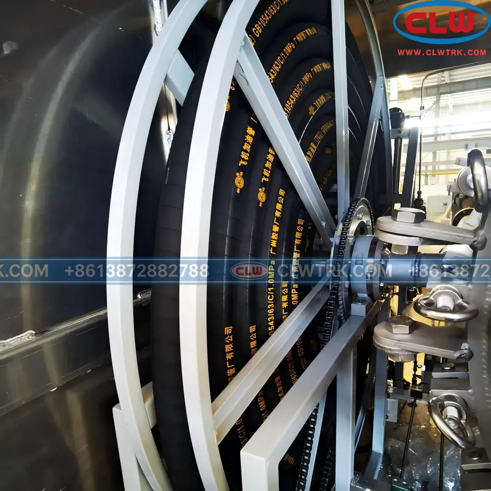
| Hose Reel | Manual, electric or hydraulic hose reel |
| Refueling Nozzle | Underwing coupler or overwing nozzle |
| Safety System | Static bonding, grounding, emergency shut-off, anti-overflow protection |
| Control System | Manual, pneumatic or electrical control |
| Additive System | Optional additive injection system |
| Loading System | Top loading or bottom loading |
| Bottom Loading Interface | Optional API bottom loading adapter |
| Platform | Optional lifting platform |
| Operating Temperature | Customized according to local climate conditions |
| Chassis Option | HOWO, Shacman, FAW, Dongfeng, Isuzu or other brands |
| Steering | Left-hand drive or right-hand drive |
| Application | Airport, airfield, helicopter base, aviation fuel service |
Final specifications depend on chassis payload, axle load, tank material, equipment weight, required flow rate, emission standard and operating environment.
Reference Standards and Design Considerations
Aircraft refueling vehicles require stricter safety, filtration and inspection control than general fuel tanker trucks. According to project requirements, the 6×4 aircraft refueler can be designed with reference to recognized aviation fuel service practices and technical standards.
Aviation Fuel Service Standards
The safety design, operating layout and refueling system can refer to:
•NFPA 407 — Standard for Aircraft Fuel Servicing
•JIG Guidelines — aviation fuel handling and into-plane operation practices
•ICAO airport ground safety practices
•Local airport fuel handling procedures
•Fuel supplier technical specifications
These references are related to static control, fuel transfer, emergency shutdown, spill prevention, fire safety, hose operation and refueling procedures.
Note: Final compliance depends on selected components, destination regulations, airport authority requirements and actual project specifications.
Filtration and Hose References
For aviation fuel filtration and hose configuration, the system may refer to:
•EI 1581 filter separator performance requirements
•API/IP 1581 aviation fuel filtration references
•EI 1529 aviation fuel hose requirements
These standards are important for filter separator selection, fuel cleanliness control, aviation fuel hose compatibility and refueling system reliability.
Aviation Fuel Safety System
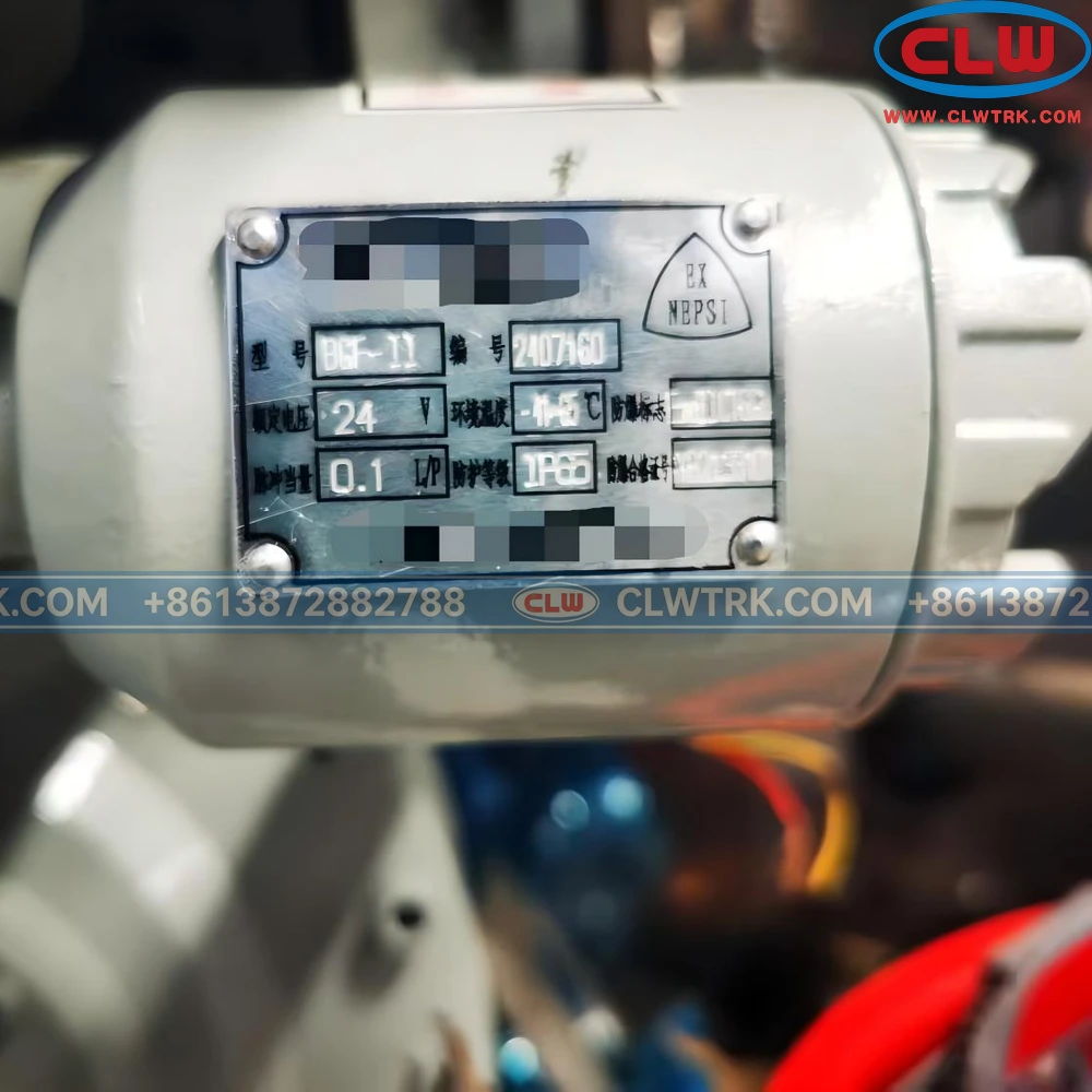
Safety is a core part of aircraft refueler design. The system should help control static electricity, overfilling, fuel leakage, incorrect operation and emergency fuel shutdown.
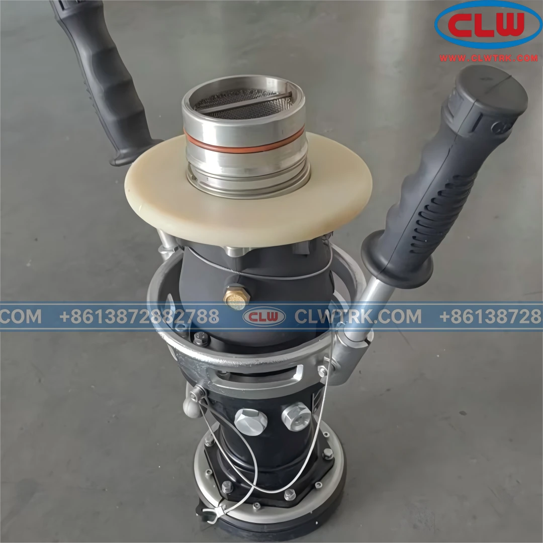
Static Bonding and Grounding
The truck can be equipped with static bonding and grounding devices, including grounding reel, bonding cable and grounding clamp. Before loading, unloading or aircraft refueling, grounding and bonding help reduce static electricity risk caused by fuel flow, hose movement and refueling connection.
Common configuration includes:
•Static grounding reel
•Bonding cable and clamp
•Grounding indicator if required
•Anti-static hose
•Conductive pipeline connection
•Safety operation labels
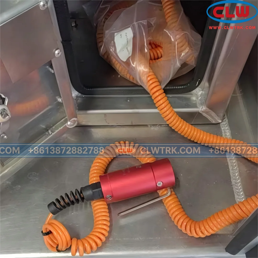
Emergency Shut-Off and Deadman Control
The aircraft refueler can be equipped with emergency stop devices and deadman control. These systems are designed to stop fuel flow when an unsafe condition occurs or when the operator releases the control handle.
Available configurations include:
•Emergency stop button
•Pneumatic emergency shut-off valve
•Manual emergency shut-off valve
•Deadman control handle
•Pump stop interlock
•Valve closing interlock
Deadman control is commonly used in aircraft refueling operations to avoid unattended or uncontrolled fuel transfer.
Anti-Overflow Protection
Anti-overflow protection helps reduce fuel spill risk during tank loading and fuel transfer. For bottom loading applications, the system can be configured with:
•Overfill sensor
•Bottom loading valve
•API bottom loading adapter
•Loading interlock
•High-level alarm
•Vapor recovery interface if required
•Pressure-vacuum vent
This configuration improves loading safety and supports cleaner fuel handling operations.
Fire Safety and Explosion-Proof Components
Because aviation fuel is flammable, fire safety accessories and explosion-proof electrical components can be selected according to operating environment and project requirements.
Optional configuration includes:
•Fire extinguishers
•Fire extinguisher brackets
•Warning labels
•Reflective markings
•Anti-slip walkway
•Safety handrails
•Explosion-proof lights if required
•Protected wiring harness
•Sealed electrical junction boxes
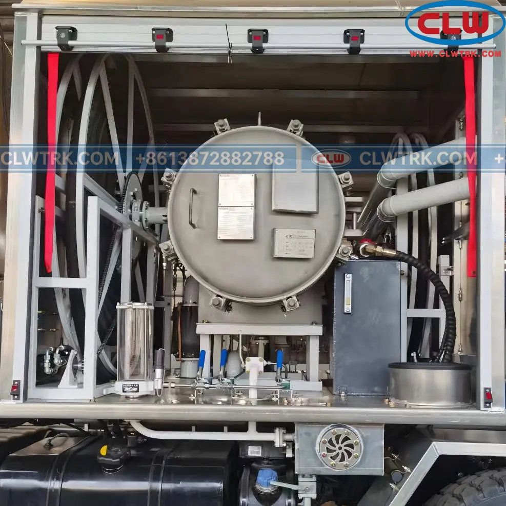
Aviation Fuel Filtration System
Clean fuel delivery is one of the most important functions of an aircraft refueler. The filtration system is used to reduce free water, solid particles and contamination risk before fuel enters the aircraft.
Filter Separator
The 6×4 aircraft refueler can be equipped with a filter separator selected according to fuel type, required flow rate, working pressure and filtration requirement.
Key selection factors include:
•Flow rate
•Fuel type
•Working pressure
•Water separation performance
•Particle filtration efficiency
•Filter element specification
•Maintenance accessibility
The filter separator is usually installed in the pump room together with pressure gauges, drain valve, sampling point and monitoring instruments.
Differential Pressure Monitoring
The filtration system can be equipped with a differential pressure gauge to monitor the pressure difference before and after the filter element. A rising differential pressure may indicate filter blockage or the need for inspection.
Common monitoring components include:
•Differential pressure gauge
•Inlet pressure gauge
•Outlet pressure gauge
•Drain valve
•Sampling point
•Air eliminator
•Filter element replacement indicator if required
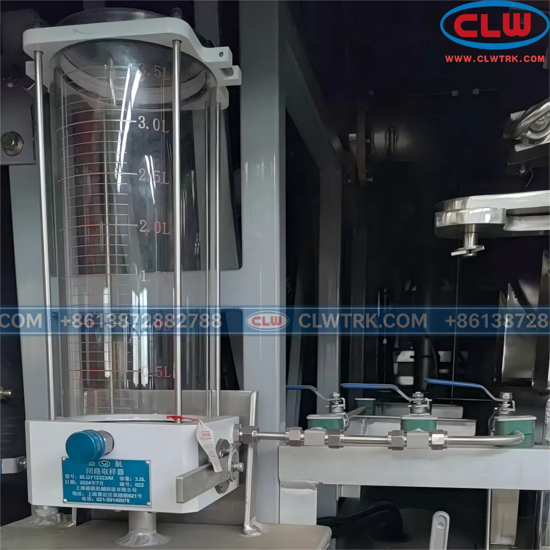
Fuel Sampling and Drain Points
Fuel sampling and drain points help support daily inspection, water removal and fuel quality control.
Typical arrangement includes:
•Tank bottom drain
•Filter separator drain
•Fuel sampling point
•Water detection point
•Pipeline drain point
•Easy-access inspection port
This design is especially important for Jet A-1 and aviation kerosene refueling service.
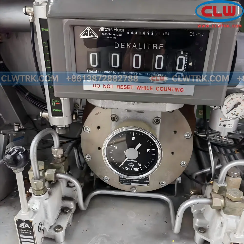
Fuel Metering System
Accurate fuel metering is required for fuel delivery records, inventory control and refueling management. The 6×4 aircraft refueler can be equipped with mechanical or digital flow meter.
Mechanical Flow Meter
A mechanical flow meter provides stable measurement with simple operation and easy maintenance.
Main features include:
•Clear local reading
•Reliable structure
•Convenient maintenance
•Suitable for standard refueling operations
Digital Flow Meter
A digital flow meter can provide advanced data display and management functions.
Optional functions include:
•Digital display
•Preset fueling
•Pulse output
•Data recording
•Printer connection
•Fuel management interface if required
Metering Calibration and Test
The metering system can be tested before delivery. Inspection items may include:
•Flow meter installation check
•Pipeline leakage test
•Flow rate test
•Meter reading test
•Calibration check if required
•Operation test before shipment
Regular calibration is recommended during service to maintain measurement accuracy.
Additive Injection System
An optional additive injection system can be installed for controlled dosing of approved aviation fuel additives during fuel transfer or refueling operation.
Additive Applications
Depending on fuel service requirements, aviation fuel additives may include:
•Anti-static additive
•Fuel system icing inhibitor
•Corrosion inhibitor
•Lubricity improver
•Other approved aviation fuel additives
The additive type, dosage and injection method should follow fuel supplier instructions and applicable aviation fuel regulations.
Controlled Dosing Configuration
The additive injection system may include:
•Additive storage tank
•Additive injection pump
•Dosing control unit
•Flow-proportional injection
•Additive pipeline
•Check valve
•Calibration interface
•Level indicator
•Maintenance drain point
This configuration is useful for cold climate operation or projects requiring specific fuel treatment procedures.
Climate Adaptability
Aircraft refueler trucks may operate in hot, cold, humid, dusty or high-altitude environments. The operating temperature range and climate conditions should be confirmed before production.
Cold Region Configuration
For low-temperature environments, optional configuration includes:
•Low-temperature resistant fuel hose
•Cold-resistant seals and gaskets
•Low-temperature hydraulic oil
•Fuel system icing inhibitor compatibility
•Protected or insulated pipelines
•Engine cold start support
•Battery protection
•Anti-freezing design for control components
Hot Region and Desert Configuration
For hot or dusty environments, optional configuration includes:
•High-temperature resistant hose
•Heat-resistant seals
•Enhanced engine cooling system
•Dust protection for key components
•Protected air intake system
•Heat-resistant paint or coating
•Heavy-duty air filter according to chassis option
Coastal and Humid Area Protection
For coastal or humid areas, corrosion protection can be strengthened with:
•Anti-corrosion coating
•Stainless steel components
•Aluminum alloy tank option
•Protected electrical connectors
•Sealed control cabinet
•Corrosion-resistant fasteners
•Enhanced paint system